Civil Engineering is a professional engineering discipline that deals with the design, construction, and maintenance of the physical and naturally built environment, including public works such as roads, bridges, canals, dams, airports, sewerage systems, pipelines, structural components of buildings, and railways. Civil Engineering takes place in the public sector from municipal through to national governments, and in the private sector from individual homeowners through to international companies.
Civil engineering is the application of physical and scientific principles for solving the problems of society, and its history is intricately linked to advances in the understanding of physics and mathematics throughout history. Because civil engineering is a wide-ranging profession, including several specialized sub-disciplines, its history is linked to knowledge of structures, materials science, geography, geology, soils, hydrology, environment, mechanics and other fields.


Civil Engineering Software:
Many software programs are available for each discipline of Civil Engineering. Most civil engineers practice in specialized subsets of civil engineering, such as geotechnical engineering, structural engineering, transportation engineering, hydraulic engineering, environmental engineering, project and construction management and land surveying.
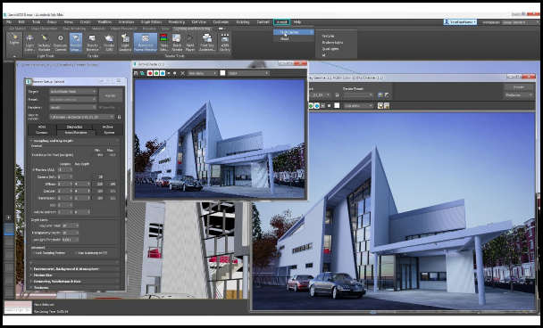
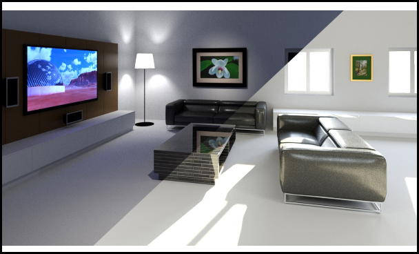
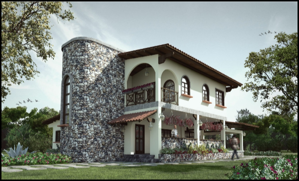
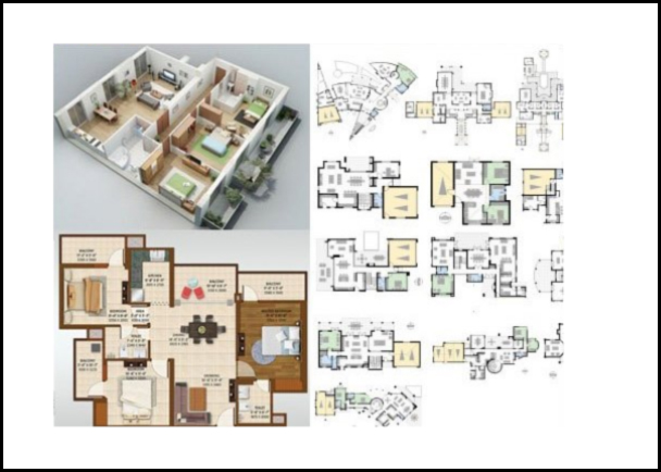
Autodesk 3ds Max, formerly 3D Studio and 3D Studio Max, is a professional 3D computer graphics program for making 3D animations, models, games, and images. It is developed and produced by Autodesk Media and Entertainment. It has modeling capabilities and flexible plugin architecture and can be used on the Microsoft Windows platform. It is frequently used by video game developers, many TV commercial studios and architectural visualization studios. It is also used for movie effects and movie pre-visualization. For its modeling and animation tools, the latest version of 3ds Max also features shaders (such as ambient occlusion and subsurface scattering), dynamic simulation, particle systems, radiosity, normal map creation and rendering, global illumination, a customizable user interface, new icons, and its own scripting language.
|
|
Each chapter begins with concepts and learning objectives, and then moves into an easy way supported by full–colour and real-world exercises. You will create actual animations as you learn a retro–Style Alarm clock and more while you conquer the techniques of Modeling, Rigging, Animating, Rendering, and Architectural Visualization. When you′re finished, you′ll also have a head start on preparing for the Autodesk 3DS MAX Certified Professional exam.
Learn these Autodesk 3ds Max essentials and more:
● 1. Introduction to 3ds Max Landscaping and modeling
●
2. Modeling using basic using Compound Objects
primitives Construct using
●
3. Transforming objects Architectural objects
●
4. Customizing working units Views – Lights and Cameras
●
5. Arranging objects using Textures – Basic & Advance
utility tools Particle Systems & Forces
●
6. Modeling using parametric Importing other formats
modifiers Basics of Animation
●
7. Editing Poly Models – using Walk-through
Caddy Interface
●
8. Advanced Rendering
●
9. Spline modeling
|
|
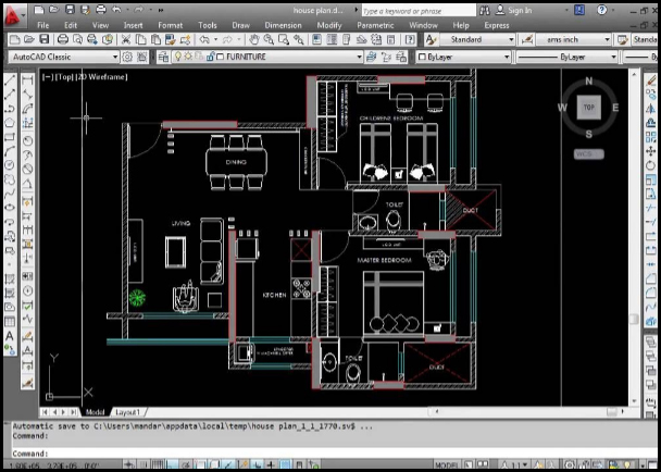
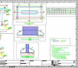
AutoCAD is a commercial computer-aided design (CAD) and drafting software application. Developed and marketed by Autodesk, AutoCAD was first released in December 1982 as a desktop app running on microcomputers with internal graphics controllers. Before AutoCAD was introduced, most commercial CAD programs ran on mainframe computers or minicomputers, with each CAD operator working at a separate graphics terminal. Since 2010, AutoCAD was released as a mobile- and web app as well, marketed as AutoCAD 360. AutoCAD is used across a wide range of industries, by Architects, Project managers, Engineers, Graphic Designers, City Planners and many other professionals.
Features:
● 1. 3D modeling concepts in Materials, lights & rendering
●
2. AutoCAD Working with images
●
3. Understand and use viewpoint Import and export
and UCS
●
4. Wireframe modeling
●
5. Solid modeling & editing
●
6. Mesh modeling & editing
●
7. Surface modeling & editing
●
8. Create & manage 2D views
from 3D models
|
|
AutoCAD is a commercial computer-aided design (CAD) and drafting software application. Developed and marketed by Autodesk, AutoCAD was first released in December 1982 as a desktop app running on microcomputers with internal graphics controllers. Before AutoCAD was introduced, most commercial CAD programs ran on mainframe computers or minicomputers, with each CAD operator working at a separate graphics terminal. Since 2010, AutoCAD was released as a mobile- and web app as well, marketed as AutoCAD 360. AutoCAD is used across a wide range of industries, by Architects, Project managers, Engineers, Graphic Designers, City Planners and many other professionals.
Features:
●
1. Introduction Isometric drawings
●
2. File management Perspective drawings
●
3. Orthographic drawings Annotations and Dimensions
●
4. View management Team work
●
5. Display management Layout management
●
6. Layer management Publish and Plot
●
7. Selection methods
●
8. Parametric drawings
●
9. Symbol creation using block
●
10. BOM / Joinery details creation
|
|
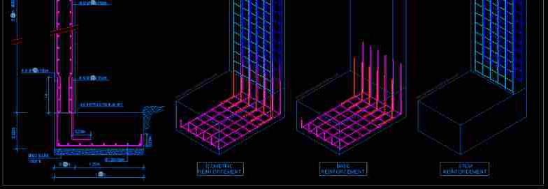
AutoCAD is a commercial computer-aided design (CAD) and drafting software application. Developed and marketed by Autodesk, AutoCAD was first released in December 1982 as a desktop app running on microcomputers with internal graphics controllers. Before AutoCAD was introduced, most commercial CAD programs ran on mainframe computers or minicomputers, with each CAD operator working at a separate graphics terminal. Since 2010, AutoCAD was released as a mobile- and web app as well, marketed as AutoCAD 360. AutoCAD is used across a wide range of industries, by Architects, Project managers, Engineers, Graphic Designers, City Planners and many other professionals.
|
|
AutoCAD is licensed, for free, to students, educators, and educational institutions, with a 36-month renewable license available. The student version of AutoCAD is functionally identical to the full commercial version, with one exception: DWG files created or edited by a student version have an internal bit-flag set (the "educational flag"). When such a DWG file is printed by any version of AutoCAD (commercial or student) older than AutoCAD 2014 SP1, the output includes a plot stamp/banner on all four sides. Objects created in the Student Version cannot be used for commercial use.
| TOPICS |
● INTRODUCTION | ● PREVIOUS |
|
|
TOPICS |
● Introduction Beam |
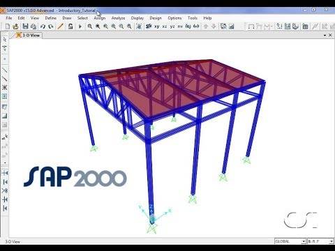
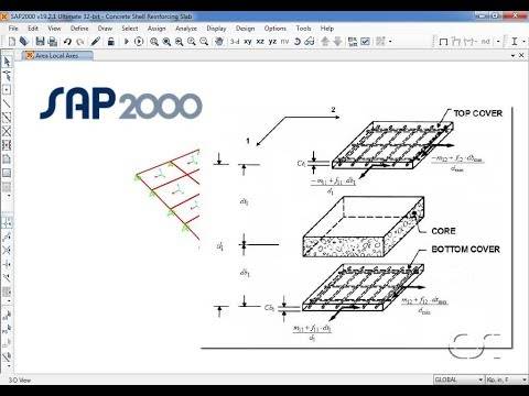
SAP2000 is general-purpose civil-engineering software ideal for the analysis and design of any type of structural system. ... Created by engineers for effective engineering, SAP2000 is the ideal software tool for users of any experience level, designing any structural system. SAP2000 is a general purpose finite element program which performs the static or dynamic, linear or nonlinear analysis of structural systems. It is also a powerful design tool to design structures following AASHTO specifications, ACI and AISC building codes. SAP is an ERP (Enterprise Resource Planning) software by the same name of the company. SAP is a german acronym which is spelled in English as “Systems, Applications and Products in data processing”. The best place to study SAP is through its certification programs
|
|
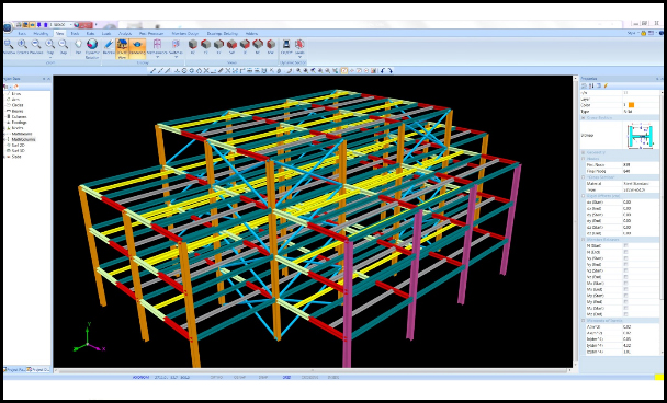
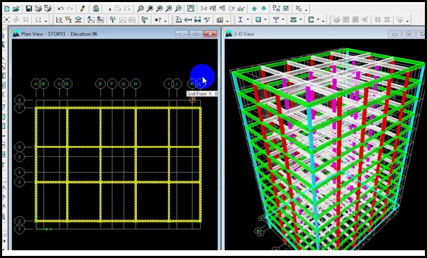
The innovative and revolutionary new ETABS is the ultimate integrated software package for the structural analysis and design of buildings. Incorporating 40 years of continuous research and development, this latest ETABS offers unmatched 3D object based modeling and visualization tools, blazingly fast linear and nonlinear analytical power, sophisticated and comprehensive design capabilities for a wide-range of materials, and insightful graphic displays, reports, and schematic drawings that allow users to quickly and easily decipher and understand analysis and design results.
From the start of design conception through the production of schematic drawings, ETABS integrates every aspect of the engineering design process. Creation of models has never been easier - intuitive drawing commands allow for the rapid generation of floor and elevation framing. CAD drawings can be converted directly into ETABS models or used as templates onto which ETABS objects may be overlaid.
Design of steel and concrete frames (with automated optimization), composite beams, composite columns, steel joists, and concrete and masonry shear walls is included, as is the capacity check for steel connections and base plates. Models may be realistically rendered, and all results can be shown directly on the structure. Comprehensive and customizable reports are available for all analysis and design output, and schematic construction drawings of framing plans, schedules, details, and cross-sections may be generated for concrete and steel structures.
ETABS provides an unequalled suite of tools for structural engineers designing buildings, whether they are working on one-story industrial structures or the tallest commercial high-rises. Immensely capable, yet easy-to-use has been the hallmark of ETABS since its introduction decades ago, and this latest release continues that tradition by providing engineers with the technologically-advanced, yet intuitive, software they require to be their most productive.
|
|
Learn these ETABS essentials and more:
●
1. Introduction to Structural Water Tank Design
●
2. Engineering Slab Design
●
3. Introduction to STAAD.Pro V8i Staircase Design
●
4. Model Generation and Editing Shear wall Design
●
5. Assigning loads Bridge Deck design using
●
6. Automatic load generations: STAAD.Beava
●
Slab, Wind and Moving loads Steel Design
●
7. Creating Load Combinations Introduction
●
8. Concrete Design Steel Frame Structure Design
●
9. Column and Beam design Overhead Transmission Line
Seismology Towers Design.
●
10. Seismic Analysis and Design Steel Structure design with
●
11. Pushover Analysis
●
12. Dynamic Analysis
●
13. Foundation Designs
●
14. Response Spectrum
●
15. Isolate, Combined, Strip, Mat and
●
16. Time History Analysis Pile Cap
●
17. FEM / FEA Report Generation and Plotting
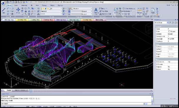
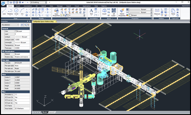
GstarCAD is well-known alternative CAD software of high compatibility with ACAD. With 25 years of continuous improvement and lean innovation, today GstarCAD is far ahead in performance, stability and other key indicators and becomes leading CAD software in the world. With new technologies, innovative features and outstanding performance, the DWG-based Collaborative Design of GstarCAD helps improve project design efficiency and significantly reduce error and cost.
Advantages of GstarCAD: Advantages of GstarCAD:
● Drawing data incremental storage and transmission
● Multi-person and multi-direction drawing reference
● Timely, synchronous and asynchronous drawing data update
● Smart drawing version management and tracing
● Easy check of design changes in reference drawings
● Convenient project import and export.
|
|
TOPICS |
● INTRODUCTION | ● PREVIOUS |
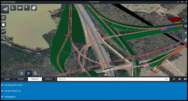
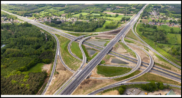
Bentley MXROAD is an advanced, string-based modeling tool that enables the rapid and accurate design of all road types. With MXROAD, you can quickly create design alternatives to build the ideal road system. After a final design alternative is selected, you can automate much of the design detailing process, saving time and money.
At its core, MXROAD uses 3D string modeling technology—a powerful yet concise method of creating 3D surfaces. The interoperable database allows engineers to create and annotate 3D project models in the most popular AEC platforms or in Windows. This means that you can work on the project within one environment, save it, and open it seamlessly in another environment with no loss of data.
Design Creativity- Bentley MXROAD’s dynamic placement and change functionality speeds the creation of 2D and 3D alignments. This “rubber band” flexibility promotes design creativity and the assessment of alternatives with quick cut/fill calculations. The end result is better quality design.
Intersection Design- Intersection design, along with other functionality in MXROAD, is string-model based. This gives you the ability to dynamically re-grade intersections as needed. Problem areas can be resolved during the design phase rather than incurring the high cost of rework onsite.
Superelevation Design- The Bentley MXROAD automated approach to superelevation design is fast and effective. Standards for superelevation can be put into a rules file for the quick application of the correct local, company, and project standards. This allows for efficiency without limiting your ability to use engineering judgement.
Pavement Layer Generator and Volumetrics- The Pavement Layer Generator models the roadway pavement construction complete with variable pavement configurations across and along the road. Volumes are produced as a by-product of the design process, delivering the information required for bids and enabling quick, accurate reactions to bid situations.
Design Rules- Built-in design rules allow you to apply local, company, and project standards, offering both time savings and greater flexibility. You can customize and override these standards as needed for greater flexibility in unusual design situations.
MX Command Language and Input Files- The MX Command Language uses simple, repeatable commands that can be recorded and replayed using Wizards. This powerful, unique MXROAD feature saves time on reiterating designs. New designs can be quickly created through the use of input files.
|
|
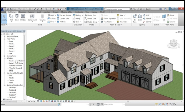
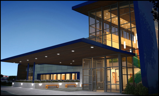
Autodesk Revit is a building information modelling (BIM) software for Architects, Landscape Architects, Structural Engineers, MEP Engineers, Designers and contractors. The software allows users to design a building and structure and its components in 3D, annotate the model with 2D drafting elements, and access building information from the building model's database. Revit is 4D BIM capable with tools to plan and track various stages in the building's lifecycle, from concept to construction and later maintenance and/or demolition.
|
|
Revit includes categories of objects ('families' in Revit terminology). These fall into three groups:
System Families, such as walls, floors, roofs and ceilings, built inside a project Loadable families/components, which are built with primitives (extrusions, sweeps, etc.) separately from the project and loaded into a project for use In-Place Families, which are built in-situ within a project with the same toolset as loadable components.
An experienced user can create realistic and accurate families ranging from furniture to lighting fixtures, as well as import existing models from other programs. Revit families can be created as parametric models with dimensions and properties. This lets users modify a given component by changing predefined parameters such as height, width or number in the case of an array. In this way a family defines a geometry that is controlled by parameters, each combination of parameters can be saved as a type, and each occurrence (instance in Revit) of a type can also contain further variations. For example, a swing door may be a Family. It may have types that describe different sizes, and the actual building model has instances of those types placed in walls where instance-based parameters could specify the door hardware uniquely for each occurrence of the door.
When a user makes a building, model, or any other kind of object in Revit, they may use Revit's rendering engine to make a more realistic image of what is otherwise a very diagrammatic model. This is accomplished by either using the premade model, wall, floor, etc., tools, or making their own models, walls, materials, etc. Revit comes with a plethora of predefined materials, each of which can be modified to the user's desires. The user can also begin with a "Generic" material. With this, the user can set the rotation, size, brightness, and intensity of textures, gloss maps (also known as shinemaps), transparency maps, reflection maps, oblique reflection maps, hole maps, and bump maps, as well as leaving the map part out and just using the sliders for any one (or all or none) of the aforementioned features of textures.
What are the advantages of utilizing Revit Architecture?
The BIM work process offered by Revit Architecture boosts efficiency as well as streamlines your outline and documentation work processes speeding ventures from configuration to fulfilment while mechanizing redesigns over your model with a solitary outline change. Revit Architecture offers different instruments and elements that can improve efficiency, for example, Physical Materials for Building Performance Analysis, Autodesk 360 Integration, Work sharing, Construction Modeling, Bidirectional Associativity, Parametric Components, and substantially more.
How is Revit Architecture utilized?
Revit Architecture is utilized by draftsmen and other building experts to decrease hazard, acquire knowledge into how structures will perform before development starts, grow better quality outlines, and enhance venture conveyance. For instance, a school of design may utilize Revit Architecture as the product of decision to help its full-time understudies increase certifiable experience utilizing a BIM work process to manufacture high-affect 3D models. On account of a building and engineering administrations firm, Revit Architecture might be utilized to quick track the mind boggling outline and development of a building that wraps around refinery preparing hardware and consider an abnormal state of future upkeep and upgrades. At last, Revit Architecture is utilized to make exact building outlines while minimizing the time it takes to arrange and plan in a virtual situation. This, thus, permits thoughts to be worked through speedier and keeps up better consistency crosswise over activities.
Learn these essentials and more:
●
1. Introduction to BIM & Revit Sheets and Title Blocks
●
2. Architecture Views, Camera, Walk-through,
●
3. Place and modify Walls & Render & Solar Study
●
4. Complex Walls In-Place Families
●
5. Add and modify Wall Profiles Family Creation
●
6. Place Doors, Windows & Site Design
Components
●
7. Link Projects & Collaboration
●
8. Dimensions and Constraints
●
9. Design Phase
●
10. Create Floors and Ceilings
●
11 .Realistic Presentations
●
12. Curtain Walls & Stairs
●
13. Import & Export
●
14. Conceptual Models
●
15. Annotation & Schedules
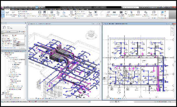
Autodesk Revit MEP is a single software application that aids a BIM (Building Information Modeling) workflow from theory to construction. It was created by Autodesk for professionals who engage in MEP (Mechanical, Electrical, and Plumbing) Engineering. Autodesk Revit is a parametric building modeler which is able to leverage dynamic information in intelligent models — allowing complex building systems to be a precisely designed and verified in less amount of time. It allows users to draw a building, structure and its constituents in 3D, note the model with 2D drafting elements, and access building information from the building model's database.
Powerful, resilient and resourceful, Autodesk Revit MEP has helped architects completely revamp the way buildings are designed, constructed and even demolished. It can handle everything from preliminary 2D layouts and project conception to final 3D renderings and ultimately destruction. With the recent resurgence in the construction industry, people who opt for Autodesk Revit MEP training are in huge demand all over the world. Autodesk Revit MEP training is necessary for every aspiring architect. Learning Autodesk Revit, however, is not very simple. Fortunately, with Canter CADD Autodesk Revit MEP training, anyone can learn Autodesk Revit with just a few weeks of hard work.
Understanding the scope of Autodesk Revit.
● Understanding BIM model is an important part of learning Autodesk Revit.
● Autodesk Revit MEP has very specific applications in the industry. So, practice for the model that works in the real world is important.
● Learning the basics of architectural theory – the how’s and why’s of building design is also important.
|
|
TOPICS
|
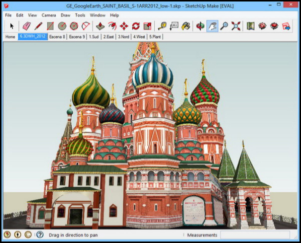
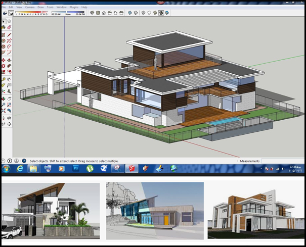
SketchUp, formerly Google SketchUp, is a 3D modeling computer program for a wide range of drawing applications such as architectural, interior design, landscape architecture, civil and mechanical engineering, film and video game design. SketchUp is owned by Trimble Inc., a mapping, surveying and navigation equipment company. There is an online library of free model assemblies (e.g. windows, doors, automobiles), 3D Warehouse, to which users may contribute models. The program includes drawing layout functionality, allows surface rendering in variable "styles", supports third-party "plug-in" programs hosted on a site called Extension Warehouse to provide other capabilities (e.g. near photo-realistic rendering) and enables placement of its models within Google Earth.
3D Warehouse is an open library in which SketchUp users may upload and download 3D models to share. The models can be downloaded right into the program without anything having to be saved onto your computer's storage. File sizes of the models can be up to 50 MB. Anyone can make, modify and re-upload content to and from the 3D warehouse free of charge. All the models in 3D Warehouse are free, so anyone can download files for use in SketchUp or even other software such as AutoCAD, Revit and ArchiCAD - all of which have apps allowing the retrieval of models from 3D Warehouse. Since 2014 Trimble has launched a new version of 3D Warehouse where companies may have an official page with their own 3D catalogue of products. Trimble is currently investing in creating 3D developer partners in order to have more professionally modelled products available in 3D Warehouse. According to the Trimble, 3D Warehouse is the most popular 3D content site on the web. SketchUp designers may visit 3D Warehouse to discover new products or for inspiration when designing their own.
|
|
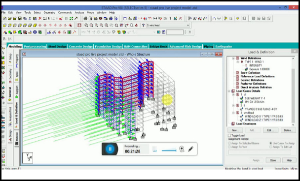
STAAD.Pro is a structural analysis and design software application originally developed by Research Engineers International in 1997. In late 2005, Research Engineers International was bought by Bentley Systems.
STAAD.Pro is one of the most widely used structural analysis and design software products worldwide. It supports over 90 international steel, concrete, timber & aluminium design codes.
It can make use of various forms of analysis from the traditional static analysis to more recent analysis methods like p-delta analysis, geometric non-linear analysis, Pushover analysis (Static-Non Linear Analysis) or a buckling analysis. It can also make use of various forms of dynamic analysis methods from time history analysis to response spectrum analysis. The response spectrum analysis feature is supported for both user defined spectra as well as a number of international code specified spectra.
Additionally, STAAD.Pro is interoperable with applications such as RAM Connection, AutoPIPE, SACS and many more engineering design and analysis applications to further improve collaboration between the different disciplines involved in a project. STAAD can be used for analysis and design of all types of structural projects from plants, buildings, and bridges to towers, tunnels, metro stations, water/wastewater treatment plants and more.
|
|
TOPICS |
●1. Introduction to Structural Water Tank Design |