Mechanical engineering is the discipline that applies engineering, physics, engineering mathematics, and materials science principles to design, analyze, manufacture, and maintain mechanical systems. It is one of the oldest and broadest of the engineering disciplines.
The mechanical engineering field requires an understanding of core areas including mechanics, dynamics, thermodynamics, materials science, structural analysis, and electricity. In addition to these core principles, mechanical engineers use tools such as computer-aided design (CAD), computer-aided manufacturing (CAM), and product life cycle management to design and analyze manufacturing plants, industrial equipment and machinery, heating and cooling systems, transport systems, aircraft, watercraft, robotics, medical devices, weapons, and others. It is the branch of engineering that involves the design, production, and operation of machinery.


Mechanical Engineering Software:
Many mechanical engineering companies, especially those in industrialized nations, have begun to incorporate computer-aided engineering (CAE) programs into their existing design and analysis processes, including 2D and 3D solid modeling computer-aided design (CAD). This method has many benefits, including easier and more exhaustive visualization of products, the ability to create virtual assemblies of parts, and the ease of use in designing mating interfaces and tolerances.
Other CAE programs commonly used by mechanical engineers include product lifecycle management (PLM) tools and analysis tools used to perform complex simulations. Analysis tools may be used to predict product response to expected loads, including fatigue life and manufacturability. These tools include finite element analysis (FEA), computational fluid dynamics (CFD), and computer-aided manufacturing (CAM).
ANSYS Mechanical is a finite element analysis tool for structural analysis, including linear, nonlinear and dynamic studies.
The
software creates simulated computer models of structures, electronics,
or machine components to simulate strength, toughness, elasticity,
temperature distribution, electromagnetism, fluid flow, and other
attributes. Ansys is used to determine how a product will function with
different specifications, without building test products or conducting
crash tests. For example, Ansys software may simulate how a bridge will
hold up after years of traffic, how to best process salmon in a cannery
to reduce waste, or how to design a slide that uses less material
without sacrificing safety.
Most Ansys simulations are performed using the Ansys Workbench software. Typically Ansys users break down larger structures into small components that are each modeled and tested individually. A user may start by defining the dimensions of an object, and then adding weight, pressure, temperature and other physical properties. Finally, the Ansys software simulates and analyzes movement, fatigue, fractures, fluid flow, temperature distribution, electromagnetic efficiency, and other effects over time.
|
|
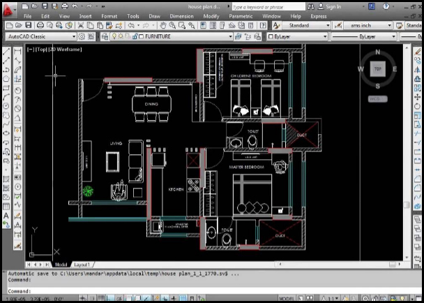
AutoCAD is a commercial computer-aided design (CAD) and drafting software application. Developed and marketed by Autodesk, AutoCAD was first released in December 1982 as a desktop app running on microcomputers with internal graphics controllers. Before AutoCAD was introduced, most commercial CAD programs ran on mainframe computers or minicomputers, with each CAD operator working at a separate graphics terminal. Since 2010, AutoCAD was released as a mobile- and web app as well, marketed as AutoCAD 360. AutoCAD is used across a wide range of industries, by Architects, Project managers, Engineers, Graphic Designers, City Planners and many other professionals.
Features:
● 1. 3D modeling concepts in Materials, lights & rendering
●
2. AutoCAD Working with images
●
3. Understand and use viewpoint Import and export
and UCS
●
4. Wireframe modeling
●
5. Solid modeling & editing
●
6. Mesh modeling & editing
●
7. Surface modeling & editing
●
8. Create & manage 2D views
from 3D models
|
|
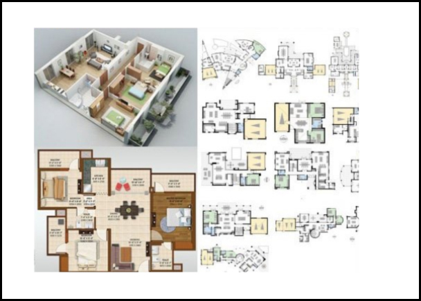
AutoCAD is a commercial computer-aided design (CAD) and drafting software application. Developed and marketed by Autodesk, AutoCAD was first released in December 1982 as a desktop app running on microcomputers with internal graphics controllers. Before AutoCAD was introduced, most commercial CAD programs ran on mainframe computers or minicomputers, with each CAD operator working at a separate graphics terminal. Since 2010, AutoCAD was released as a mobile- and web app as well, marketed as AutoCAD 360. AutoCAD is used across a wide range of industries, by Architects, Project managers, Engineers, Graphic Designers, City Planners and many other professionals.
Features:
●
1. Introduction Isometric drawings
●
2. File management Perspective drawings
●
3. Orthographic drawings Annotations and Dimensions
●
4. View management Team work
●
5. Display management Layout management
●
6. Layer management Publish and Plot
●
7. Selection methods
●
8. Parametric drawings
●
9. Symbol creation using block
●
10. BOM / Joinery details creation
|
|
Mechanical APDL has also graphics but does not require it for execution. One can do CAD modeling (very cumbersome) and FEM modeling all inside the same screen. Since everything is pretty much done via commands (kind of on the fly scripting) it is much more convenient to make loops and repeat actions (such as running hundreds of load cases and automatically write out only a few numbers from each set.
|
|
Ansys Workbench (Mechanical) is more graphics focused and geometry focused. There is less direct connection to the FEM. Workbench provides easy to learn, easy to use environment. APDL scripts are still a possible to use but it’s a bit cumbersome.
|
|
1. Introduction to CAE Buckling analysis |
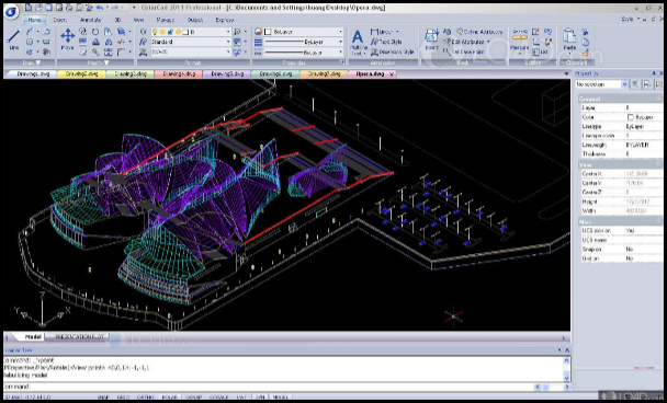
AutoCAD is a commercial computer-aided design (CAD) and drafting software application. Developed and marketed by Autodesk, AutoCAD was first released in December 1982 as a desktop app running on microcomputers with internal graphics controllers. Before AutoCAD was introduced, most commercial CAD programs ran on mainframe computers or minicomputers, with each CAD operator working at a separate graphics terminal. Since 2010, AutoCAD was released as a mobile- and web app as well, marketed as AutoCAD 360. AutoCAD is used across a wide range of industries, by Architects, Project managers, Engineers, Graphic Designers, City Planners and many other professionals.
|
|
AutoCAD is licensed, for free, to students, educators, and educational institutions, with a 36-month renewable license available. The student version of AutoCAD is functionally identical to the full commercial version, with one exception: DWG files created or edited by a student version have an internal bit-flag set (the "educational flag"). When such a DWG file is printed by any version of AutoCAD (commercial or student) older than AutoCAD 2014 SP1, the output includes a plot stamp/banner on all four sides. Objects created in the Student Version cannot be used for commercial use.
| TOPICS |
● INTRODUCTION | ● PREVIOUS |
●
1. CATIA user interface Bill of materials, balloons
●
2. Creating and editing sketches Finalizing the drawing and printing
●
3. Creating sketch based features Dress up on 2D Views
●
4. Creating transformation features Real time rendering
●
5. Creating dress up features GD&T
●
6. Creating advanced replication tools
●
7. Editing parts in assembly
●
8. Creating surface features
●
9. Generative sheetmetal design
●
10.Drawing view generation
|
|
|
|
TOPICS |
● 1. Sketcher basics Bottom-up assembly |
Hypermesh training course enables participants to work on Hypermesh 12.0 software, a computer aided engineering (CAE) simulations software platform. The training enables the trainees to create finite element models for analysis and prepare high-quality meshes in an efficient manner. This program offers the skills needed to work with geometry editing tools for preparing CAD models for the meshing process. During the Hypermesh training, the attendees will have knowledge about the BatchMeshing technique that facilitates users to mesh several files in the background to match the standards set by users.
By the end of the training, the participants will inculcate skills on the following topics:
● Finite Element Analysis (FEA)
● Shell, Tetra, and HyperMeshing
● Creating hexa and penta mesh
● Assemblies: Welding and Swapping Parts
● Topography and Topology
● Thermal, Static and Normal Mode analysis
● Preparing models for analysis and geometry for meshing
● Defining manufacturing constraints
● 2D and 3D shape optimization
● 1D and 2D size optimization
● Results visualization with HyperMesh
|
|
TOPICS |
● INTRODUCTION | ● Edit element, smooth |
Inventor software takes manufacturers beyond 3D to Digital Prototyping by giving engineers a comprehensive and flexible set of tools for 3D mechanical design, simulation, tooling, visualization and documentation. With Inventor software, engineers can integrate 2D AutoCAD® drawings and 3D data into a single digital model, creating a virtual representation of the final product that enables them to validate the form, fit, and function of the product before it is ever built. Digital Prototyping with Inventor software enables you to design, visualize, and simulate products digitally, helping you to build better products, reduce development costs, and get to market faster.
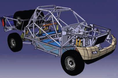
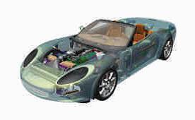
This software incorporates integrated motion simulation and assembly stress analysis, whereby users are given options to input driving loads, dynamic components, friction loads and further run the dynamic simulation to test how the product will function in a real-world scenario. These simulation tools enable users designing cars or automotive parts, for example, to optimize the strength and weight of a product, identify high-stress areas, identify and reduce unwanted vibrations, and even size motors to reduce their overall energy consumption.
Autodesk Inventor's finite element analysis feature allows users to validate the component design through testing part performance under loads. The optimization technology and parametric studies permit users to design parameters within assembly stress areas and compare the design options. Then, the 3D model is updated based on these optimized parameters.
Autodesk Inventor also uses special file formats for parts, assemblies and drawing views. The files are imported or exported in a DWG (drawing) format. However, the 2D and 3D data interchange and review format that Autodesk Inventor uses most frequently is design web format (DWF).
|
|
NX was formerly known as "Unigraphics. NX is an advanced high-end CAD/CAM/CAE, which has been owned since 2007 by Siemens PLM Software. It is used, among other tasks, for:
● Design (parametric and direct solid/surface modeling)
● Engineering analysis (static; dynamic; electromagnetic; thermal, using the finite element method; and fluid, using the finite volume method).
● Manufacturing finished design by using included machining modules.
NX is a direct competitor to CATIA, Creo, Autodesk Inventor, and SolidWorks.
|
|
Creo is a family or suite of Computer-aided design (CAD) apps supporting product design for discrete manufacturers and is developed by PTC. The suite consists of apps, each delivering a distinct set of capabilities for a user role within product development. Creo runs on Microsoft Windows and provides apps for 3D CAD parametric feature solid modeling, 3D direct modeling, 2D orthographic views, Finite Element Analysis and simulation, schematic design, technical illustrations, and viewing and visualization.
Creo Elements/Pro and Creo Parametric compete directly with CATIA, Siemens NX/Solidedge, and SolidWorks. The Creo suite of apps replaces and supersedes PTC’s products formerly known as Pro/ENGINEER, CoCreate, and ProductView. Creo has many different software package solutions and features. Creo Illustrate is a good example.
PTC began developing Creo in 2009, and announced it using the code name Project Lightning at PlanetPTC Live, in Las Vegas, in June 2010.In October 2010, PTC unveiled the product name for Project Lightning to be Creo. PTC released Creo 1.0 in June 2011.
Creo is part of a broader product development system developed by PTC. It connects to PTC’s other solutions that aid product development, including Windchill for Product Lifecycle Management (PLM), Mathcad for engineering calculations and Arbortext for enterprise publishing software.
|
|
TOPICS |
● INTRODUCTION |